
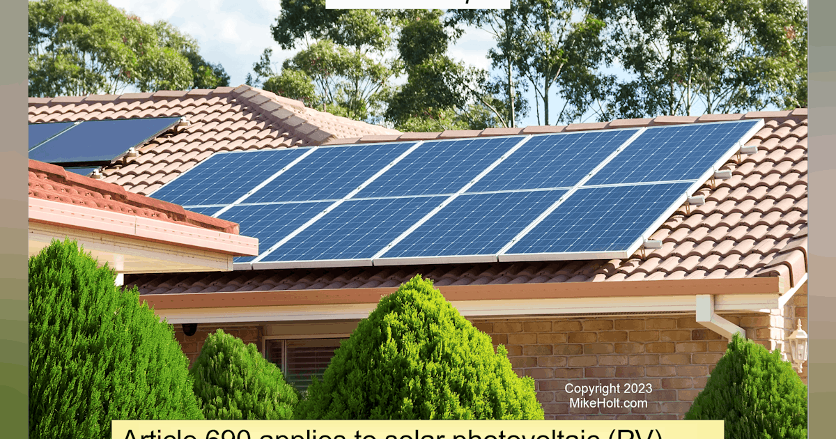
NEC Requirements for Solar — Part 1 – Electrical Construction & Maintenance (EC&M)
Grounding and bonding
This topic leads to much confusion, but some clarity is achieved by looking at the definitions in Art. 100. Grounding means you make a connection to the earth, and bonding means you make a connection to a low-impedance metallic path.
An earth connection (ground) is for the supply (e.g., a separately derived source such as a transformer). The main purpose of grounding is to provide an alternate path for large transients such as lightning.
A low-impedance connection (bond) is for the load (e.g., utilization equipment frames and enclosures). The main purpose of bonding is to remove dangerous voltage from metallic objects so undesired current cannot flow between them.
The earth is relatively high impedance when compared to the same length of copper wire, so it’s not effective as a bonding means. This is why you never drive a ground rod next to a motor instead of connect a bonding jumper to it. Bonding creates a metallic path, even if that path is part of what is called the “equipment grounding conductor” (EGC). While the EGC ultimately connects to ground, it is in reality an EGC because it is connecting equipment to a low-impedance metallic path rather than connecting equipment to the earth.
Keep this short explanation in mind when applying any bonding or grounding requirements of the NEC.
PV system DC circuits must use one or more of the following system configurations [Sec. 690.41(A)]:
(1) 2-wire circuits with one functionally grounded conductor.
(2) Bipolar circuits according to Sec. 690.7(C) with a functional ground reference (center tap).
(3) Circuits not isolated from the grounded inverter output circuit (functionally grounded inverter).
(4) Ungrounded circuits.
(5) Solidly grounded circuits as permitted in Sec. 690.41(B).
(6) Circuits protected by equipment listed and identified for the use.
Today’s inverters are typically of the “not isolated from the grounded inverter output circuit” type
[Sec. 690.41(A)(3)]. These PV systems are known as “functionally grounded inverters.” A functionally grounded PV system is often connected to ground through an electronic means that is internal to an inverter or charge controller that provides ground-fault protection.
PV system DC circuits that exceed 30V or 8A must be provided with ground-fault detector-interrupter (GFDI) protection [Sec. 690.41(B)]. If GFDI is not included in the DC-to-DC converter, the installation manual must provide a warning statement that indicates GFDI is not included.
The GFDI must provide three functions. The first is ground-fault detection. The GFDI device or system must be detect ground fault(s) in the PV system DC circuits, and be listed for providing GFDI protection. For DC-to-DC converters not listed as providing GFDI protection, where required, you must install listed GFDI protection equipment identified for the combination of the DC-to-DC converter and the GFDI device to protect the circuit.
The second is by controlling the faulted circuits in one of two ways:
(1) The current-carrying conductors of the faulted circuit must be automatically disconnected.
(2) The device providing GFDI protection fed by the faulted circuit must automatically cease to supply power to output circuits and interrupt the faulted PV system DC circuits from the ground reference in a functionally grounded system.
The third method is the GFDI equipment provides indication of ground faults at a readily accessible location.
Metal parts of PV module frames, PV equipment, and enclosures containing PV system AC and DC conductors must be connected to the circuit EGC per Sec. 690.43(A) through (D), as shown in
Fig. 2.